This is going to be a tutorial on how to work with Raspberry Pi. It is a single board computer developed in UK in association with Broadcom. It was targeted for teaching basic computer science in schools, but it is widely used in robotics, hobbyists and small monitoring activities.
Install operating system
Download the Raspberry Pi OS from https://www.raspberrypi.com/software/operating-systems I would suggest to get the headless version (Lite). This will not support a direct display port, but you will be able to login into it using ssh and work with all unix commands.
Download and unzip the img file on your local computer’s drive.
Download & Install Etcher from https://www.balena.io/etcher to flash the image on the SDcard
Install formatted MicroSDCard to your computer, Start Etcher, Select the OS Image and flash the image to the SD card.
Your image / SD card is ready to boot up the raspberry Pi, but you do not have anyway to connect to it. You will need to setup a network and enable ssh before you want to plugin the SD card in your raspberry Pi.
Connect to Raspberry Pi
Enabling SSH: Create an empty file named “ssh” no extenstions on the root location of your SD card.
Enabling Wifi: Create a file named “wpa_supplicant.conf” on the root location of your SD card
with the following content (with your wi-fi values)
network=
   ssid=”SSID”
   psk=”password”
   key_mgmt=”WPA-PSK”
}
Now go ahead and insert your SD card into the raspberry Pi and power it up.
You can now go to your home router to see connected devices to find out the IP address of your new raspberry Pi. Let’s assume the IP address which is allocated to the Raspberry Pi is 192.168.1.124
Use terminal or Putty to ssh to raspberry Pi with User=pi and password=raspberry
If you want to allow root login, you can edit the /etc/ssd/sshd_config file (in sudo mode) to
Remove: hashtag#PermitRootLogin without-password
Add: PermitRootLogin yes
Restart ssh daemon with /etc/init.d/ssh restart
Don’t forget to set a password for root now using command >passwd root
Then you can disconnect from raspberry pi and reconnect using the root user and password you chose.
GPIO PINs
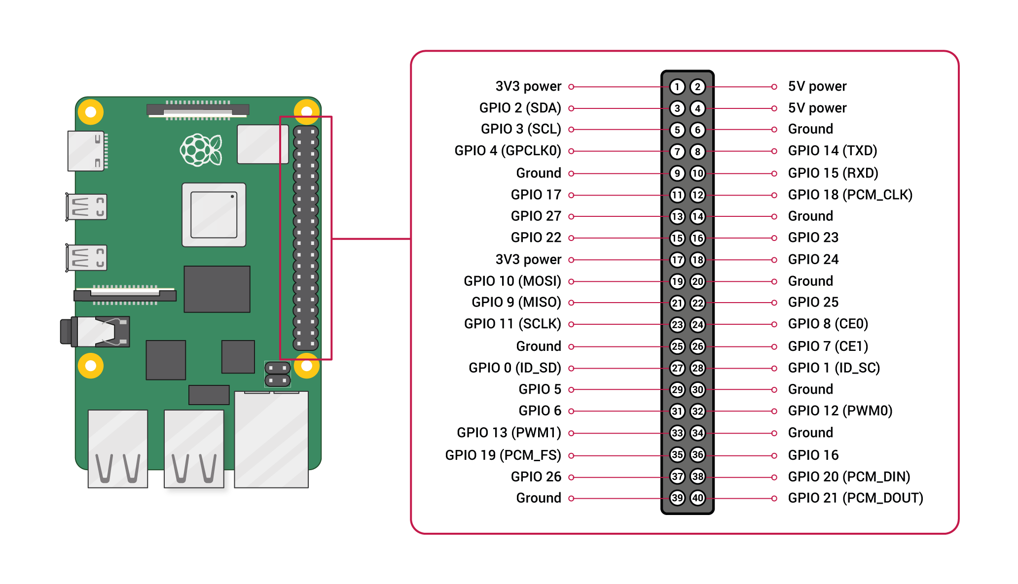
A powerful feature of the Raspberry Pi is the row of GPIO (general-purpose input/output) pins along the top edge of the board. A 40-pin GPIO header is found on all current Raspberry Pi boards. The GPIO header have a 0.1″ (2.54mm) pin pitch.
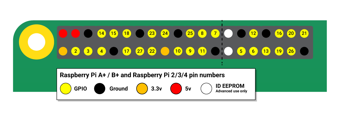
The 2 images below give a very clear information on which PIN does what. The programs can leverage either the physical PIN (Board) numbering OR the BCM (Broadcom) numbering.
Any of the GPIO pins can be designated as an input or output pin.
A Small circuit
Let’s plugin a small circuit, with a switch and a LED. We will write a python program in following order
1. Program to turn on/off LED
2. Program to detect if switch is pressed or not pressed
3. Integrate the above to turn on LED when switch is pressed and to turn it off when button is released
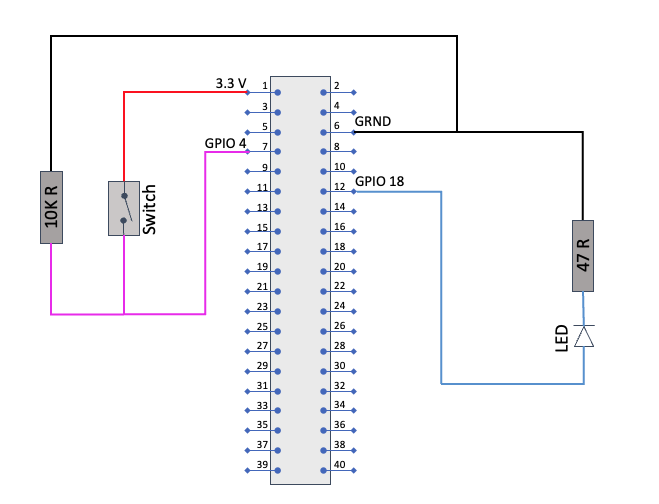
This is the circuit which we are building
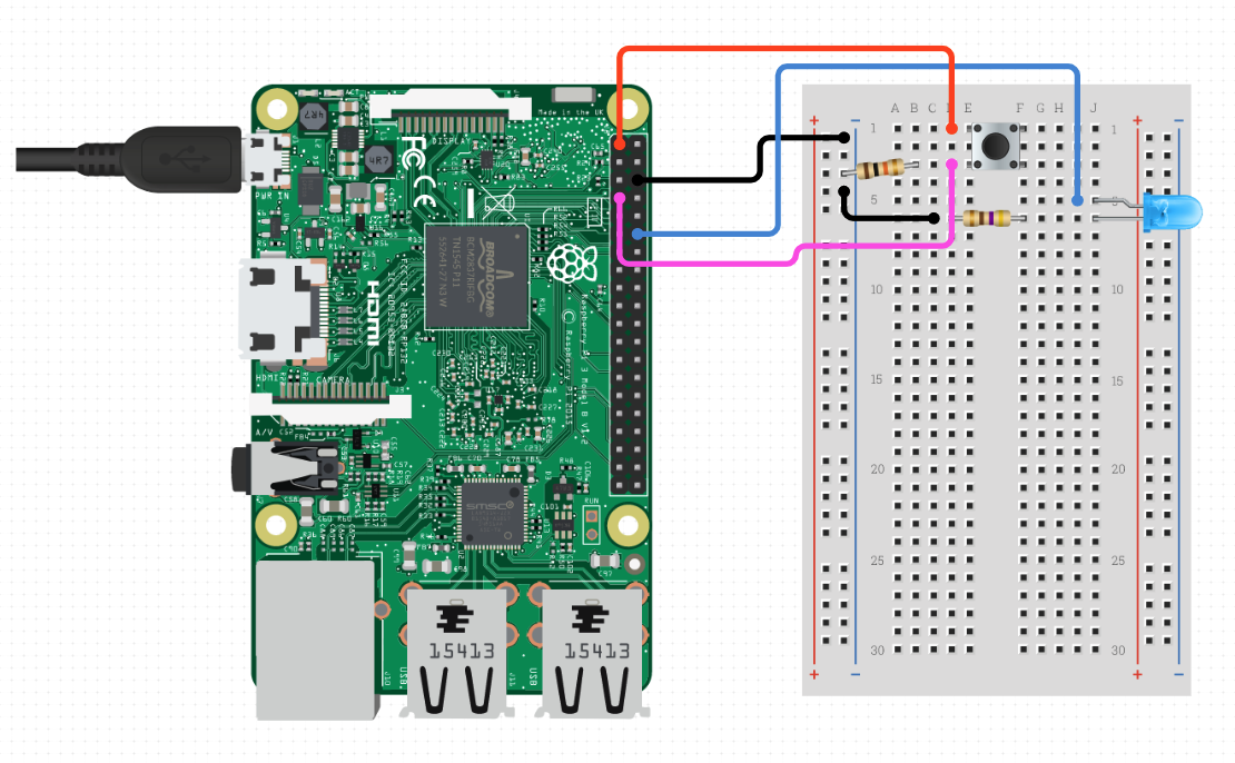
This is how it will look like on a breadboard
Install python
Python is already installed on Raspberry pi OS, but you can go ahead and run
sudo apt-get update
sudo apt-get install python3
Then we can install pip (Python package installer) to install python modules
sudo apt-get install python3-pip
Program to turn on/off LED
import RPi.GPIO as GPIO

ledOutPin = 12
GPIO.setmode(GPIO.BOARD) # use BOARD numbering
GPIO.setup(ledOutPin, GPIO.OUT)
GPIO.output(ledOutPin, GPIO.HIGH) # turn LED ON
GPIO.output(ledOutPin, GPIO.LOW) # turn LED OFF
Same with Broadcom numbering
import RPi.GPIO as GPIO

ledOutPin = 18

GPIO.setmode(GPIO.BCM) # use Broadcom numbering
GPIO.setup(ledOutPin, GPIO.OUT)
GPIO.output(ledOutPin, GPIO.HIGH) # turn LED ON
GPIO.output(ledOutPin, GPIO.LOW) # turn LED OFF
Program to detect if switch is pressed or not pressed
import RPi.GPIO as GPIO
import time

buttonInPin = 4  # GPIO 4, Board  7

GPIO.setwarnings(False)
GPIO.setmode(GPIO.BCM) # use Broadcom numbering
GPIO.setup(buttonInPin, GPIO.IN)

while True:
    buttonValue = GPIO.input(buttonInPin) # Read button state 1 (pressed), 0 (not pressed)
    if buttonValue:
          print(“Button Pressed”)
    else:
          print(“Button Not Pressed”)

    time.sleep(0.1).  # Sleep for 100 milliseconds

GPIO.cleanup()
Integrate the above to turn on LED when switch is pressed and to turn it off when button is released
import RPi.GPIO as GPIO
import time

buttonInPin = 4  # GPIO 4, Board  7
ledOutPin = 18 # GPIO 18, Board 12

GPIO.setwarnings(False)
GPIO.setmode(GPIO.BCM) # use Broadcom numbering
GPIO.setup(ledOutPin, GPIO.OUT)
GPIO.setup(buttonInPin, GPIO.IN)

while True:
    buttonValue = GPIO.input(buttonInPin) # Read button state 1 (pressed), 0 (not pressed)

    if buttonValue:
          GPIO.output(ledOutPin, GPIO.HIGH) # turn LED ON
          print(“Button Pressed”)
    else:
          GPIO.output(ledOutPin, GPIO.LOW) # turn LED OFF
          print(“Button Not Pressed”)

    time.sleep(0.1).  # Sleep for 100 milliseconds

GPIO.cleanup()
Backup and Restore
To do a backup of your SD card on mac you will need to know where your SD card is mounted on mac first
To get a list of mounts run the command “diskutil list” You will be able to identify the SD card by the disk size. Let’s assume its mounted on “/dev/disk4”
To take a backup of SD card, run command
sudo dd if=/dev/disk4 of=~/backups/rp_v1.dmgto restore the image on sd card
format the SD card
sudo newfs_msdos -F 16 /dev/disk4to restore the image to card
sudo dd if=~/backups/rp_v1.dmg of=/dev/disk4Not so complex when you know it and good enough for a bit of tinkering.
Cheers – Amit Tomar

