Arduino Uno is a microcontroller board based on the ATmega328P processor. It contains everything needed to support the microcontroller; simply connect it to a computer with a USB cable or power it with a AC-to-DC adapter or battery to get started.
Unlike Arduino, Raspberry Pi is a single board computer has its own operating system and can carry out complex operations.
Arduino Software (IDE) is a free tool to write software (sketches) to control various sensors and controllers. The IDE supports importing of third party libraries to communicate with various sensors.
There are mainly 2 types of sensor devices
Outputs – Motors, LEDs, buzzers – they have input PINs which are turned ON by passing voltage to them.
Inputs – Buttons, Temperature sensors, Pressure, humidity, sensors etc. These are directly connected to power and ground and have a data pin to read the state / data for the voltage which has to be converted to a value.
PINs
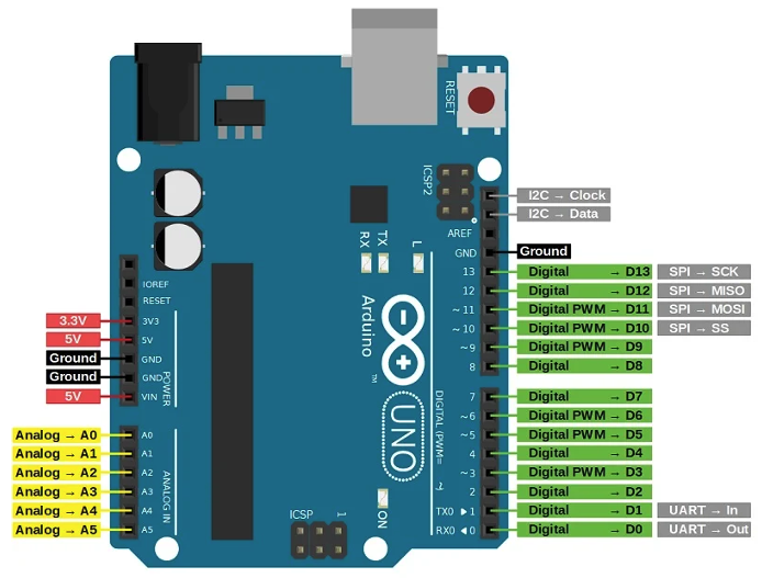
The board has 2 sets of PINs
The right hand side are
Digital pins 0-13, which can detect high/low values as input, or give out high/low signal to external devices.
- The ones with no ~ sign can read / write a High / Low value only
- The ones with a ~ sign can write a analog output using a mechanism of Pulse Width Modulation (PWM) where the signal toggles ON/OFF for the percentage of analog value.
AREF – used when you are using 3.3 volts instead of 5 volt input to tell Arduino to scale the calculations appropriately.
SCL – The clock line
SDA – The Data line
ICSP 1 header on top right is used to program the Atmega16U2 which is used for serial communication
ICSP 2 header on bottom is used to program the ATmega328P chip directly.
On the left hand side, we have power, ground, and for reading the input values for analog signal. The reading for analog value ranges from 0-1023 so if you are reading a potentiometer, you will have to scale the measurements appropriately and also use a fixed resistor to avoid burnout.
Protocols supported
Serial (UART)
the Right side pins 0 (RX) and 1 (TX) are connected to USB input through the Atmega16U2. So if your computer is not connected to USB port and the board is powered by a power supply, these 2 pins can be used for serial communication.
I2C (TWI)
I squared C / Two Wire interface was developed by Philips semiconductor, now known as NXP. Its a Fast serial interface which allows devices to be connected in a chain fashion.
SCL is the clock pin
SDA is the data pin.
It uses an addressing scheme to send data to a unique device connected in a chain.
SPI (Serial Peripheral interface)
Full duplex devices like graphics displays implement this. It uses 4 wires to communicate
2 Data lines for bi-direction communication
– MOSI – Master out Slave in
– MISO – Master in Slave out
SCL – The clock line
Slave select (Digital pin to select which device we are communicating with)
Objective
We will use 2 sensors, a temperature sensor to get the current temperature. We will use current temperature to find the speed of sound. Then we will use a ultrasonic distance sensor to find out how much time it takes the sound wave to come back. Based on that we will calculate the distance.
DHT22 sensor
A very common temperature and humidity sensor. Data Sheet
The library which we will use for it is DHT-sensor-library

HC-SR04 ultrasonic distance sensor
This sensor have 2 transducers to generate and detect ultrasonic waves.
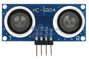
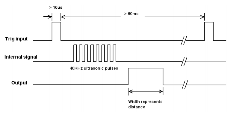
The trigger pin is used to send out a 10 micro second wave, and the sensor responds with an output wave in which the width of the HIGH value represents the time it took for the wave to go and come back.
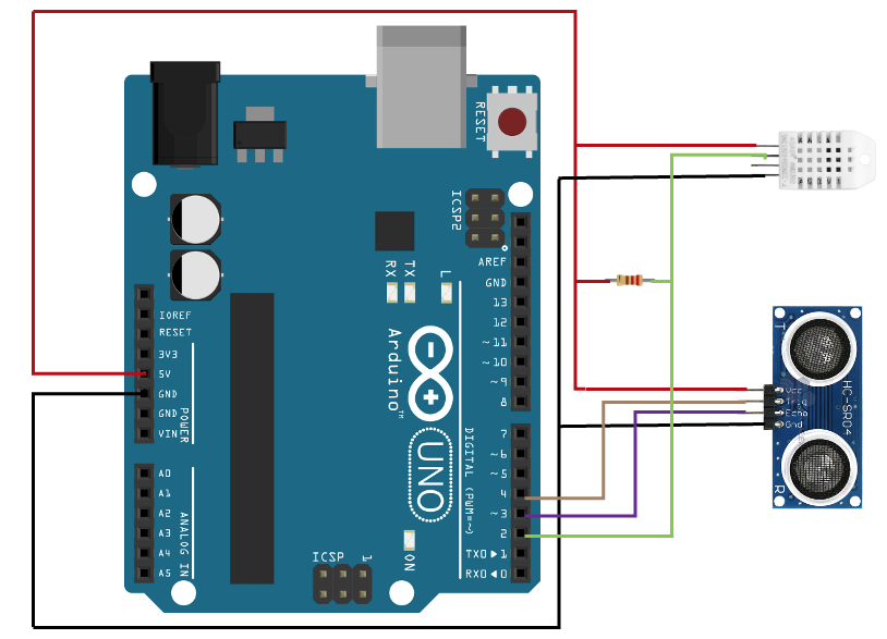
The wiring diagram
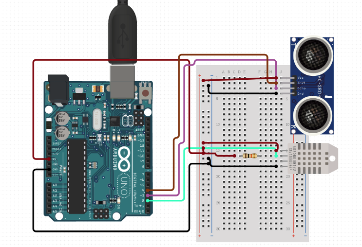
Breadboard connections
Basic sketch
There are 2 functions which are supposed to be implemented. Setup is run only once. and loop runs infinitely.
void setup() {
 Serial.begin(9600); // connects back to serial port to read / write
 Serial.print("Setup complete");
}

void loop() {
 delay(2000);       // wait 2 seconds
 Serial.println("Looping");
}
Reading the temperature
#include "DHT.h"
//add # to next 2 lines. Linkedin snippet is breaking. It's #define
define DHTPIN 2           // digital pin we are connected to
define DHTTYPE DHT22      // type of sensor we are using

DHT dht(DHTPIN, DHTTYPE);  // Initialize DHT variable.

void setup() {
  Serial.begin(9600);
  dht.begin();
}

void loop() {
  delay(2000);             // wait 2 seconds
  float h = dht.readHumidity();
  float f = dht.readTemperature(true); // true signifies we want it in farhenite
  if (isnan(f) || isnan(h)) {
    Serial.println("Failed to read data!");
    return;
  }
  Serial.print("Humidity: ");
  Serial.print(h);
  Serial.print(" %\t");
  Serial.print("Temperature: ");
  Serial.print(f);
  Serial.println(" F");
}
Reading the distance
//add # to next 2 lines. Linkedin snippet is breaking. It's #define.
define triggerPin 4
define echoPin 3

void setup() {
  Serial.begin (9600);
  pinMode(triggerPin, OUTPUT);
  pinMode(echoPin, INPUT);
}

void loop() {
  long duration;
  long distance;
  long speedOfSound = 330; // meter per sec
  digitalWrite(triggerPin, LOW);
  delayMicroseconds(50);          // trigger on low before we send the pulse
  digitalWrite(triggerPin, HIGH); // send the pulse
  delayMicroseconds(10);
  digitalWrite(triggerPin, LOW);  // down to low afte 10 micro secs
  duration = pulseIn(echoPin, HIGH); //get the duration
  // convert speed of sound to cm / micro sec
  // distance = time X speed
  distance = (duration/2) * (speedOfSound * 100 / 1000000);

  if (distance >= 400 || distance <= 2){ //Range check from data sheet
    Serial.println("Out of range value");
  } else {
    Serial.print(distance);
    Serial.println(" cm");
  }
  delay(500);
I have used the speed of sound as 330 m/s but since it is dependent on temperature, we can also have a table which can give a correct speed of sound based on temperature and humidity which we can use to plug in into our program.
Cheers – Amit Tomar

